Author name: admin

Online Water Monitoring Systems
Blogs, Water Quality Monitoring

Why Industries Are Moving Towards Online Water Monitoring Systems

Water has quietly become one of the most regulated and most scrutinised inputs in Indian industry. Plants that once treated water management as a back-end utility now face direct pressure from regulators, rising input costs, and public attention on discharge quality. In response, a growing number of factories, treatment plants, and process facilities are replacing periodic manual sampling with Online Water Monitoring Systems that report water quality continuously instead of in batches. The shift is not about technology for its own sake. It is driven by specific operational and compliance gaps that manual testing can no longer close. The Problem With Sampling on a Schedule Conventional monitoring depends on grab samples collected at fixed intervals and sent to a laboratory. Results return a day or two later, by which time the conditions that produced them have usually changed. A single sample describes one location at one moment. It says nothing about what happened overnight, during a shift change, or when an effluent valve was briefly opened. For industries, that gap carries real consequences. An off-hours discharge exceedance can go unrecorded until the next scheduled sample. A drop in treatment performance can continue for hours before anyone notices. Because corrective action only begins after lab confirmation, most responses are reactive, and the cost of a missed event arrives as a penalty, a shutdown, or reputational damage. What an Online Water Monitoring System Actually Does An Online Water Monitoring System measures water quality directly in the process or discharge stream and transmits the data continuously to operators and, where required, to regulators. A working setup combines multi-parameter sensors, a data logger or remote telemetry unit, a communication link, and a cloud or SCADA platform. Sensors track key water quality and process parameters including flow, pH, TSS, COD, ammoniacal nitrogen, dissolved oxygen, TOC (where applicable), conductivity, turbidity, nitrate, and other application-specific indicators. Where required, BOD values are estimated using surrogate correlations or specialised analysers. Communication can be established through GSM/4G/5G, Ethernet, fibre, radio telemetry, LoRaWAN, or satellite networks depending on site conditions and regulatory requirements. The platform compares each reading against defined limits and raises an alert the moment a threshold is crossed. Why Industries Are Making the Move Regulation is the strongest single driver. Since CPCB’s OCEMS directives, industries classified under 17 Highly Polluting Industry (HPI) sectors have been required to install Online Continuous Effluent Monitoring Systems (OCEMS) and transmit real-time data to CPCB and State Pollution Control Board servers. For these plants, online monitoring is no longer optional, and the systems must stay calibrated and connected to remain compliant. Beyond compliance, water is getting expensive and scarce. Continuous monitoring provides confidence in treated water quality, enabling industries to safely reuse water for cooling towers, utilities, process applications, landscaping, and other non-potable purposes. Continuous visibility also lowers risk. Live data shows exactly which stage of a process is drifting, so operators can intervene before a parameter breaches its limit. When something does go wrong, a complete time stamped record helps separate a genuine process fault from a sensor event and supports any conversation with a regulator. Water performance has also become part of how companies report on sustainability. Verifiable, continuous discharge data carries far more weight with auditors and stakeholders than a folder of periodic lab reports. Where It Is Being Deployed Industrial effluent treatment plants form the largest use case, particularly in sectors named under the OCEMS mandate such as chemicals, pharmaceuticals, textiles, sugar and distillery, pulp and paper, and power generation. The technology is widely deployed across ETPs, CETPs, STPs, cooling water systems, and ZLD plants to support continuous compliance and operational control. Within industrial facilities, the same architecture enables process water monitoring, boiler and cooling water management, inlet water quality checks, and discharge monitoring where water quality directly affects process efficiency and product quality. Utilities and municipal operators apply these systems across treatment plant outlets, distribution networks, raw water intake monitoring points, and river monitoring stations to maintain visibility over water quality and ensure regulatory compliance. What to Plan For Before Deployment Online monitoring stays reliable when a few practical points are handled early. Sensor selection should match the actual water matrix, since effluent with high solids or aggressive chemistry fouls probes faster and needs more frequent service. Calibration is not a one time task, and most parameters need verification against laboratory standards every 30 to 90 days. Communication should suit the site, with cellular for connected locations and LoRaWAN or satellite for remote ones. Where regulatory transmission is required, the integration path to CPCB and state board servers should be confirmed before installation rather than after. Integrated Monitoring, Telemetry, and Compliance Infrastructure Aaxis Nano provides integrated solutions for continuous water quality monitoring by combining online instrumentation, telemetry, and SCADA connectivity. Multi-parameter sensors from partners such as s::can and ATi deliver real-time measurements, while the Telepro platform enables data visualization, alarm management, historical trending, and automated reporting. The solution supports seamless integration with plant SCADA systems and regulatory reporting platforms, including CPCB and SPCB servers where required. From system design and commissioning to calibration and maintenance, Aaxis Nano helps ensure reliable monitoring, data integrity, and long-term compliance performance. FAQs Q1. Is an online water monitoring system mandatory for my plant? If your facility falls under one of the 17 highly polluting industry categories defined by CPCB, an Online Continuous Effluent Monitoring System with live data transmission to CPCB and state board servers is a regulatory requirement. Many other plants adopt it voluntarily for process control and water reuse. Q2. How accurate are online sensors compared with laboratory testing? For most regulated parameters, modern sensors perform close to laboratory methods when properly calibrated. Routine verification against lab standards every 30 to 90 days keeps readings reliable. Complex parameters such as heavy metals may still need laboratory confirmation. Q3. What ongoing maintenance do these systems need? Typical upkeep includes periodic probe cleaning, calibration checks, inspection of the communication link, and replacement of consumable sensor parts. Effluent with high solids or

MetriNet Water Quality Monitor
Blogs, Water Quality Monitoring

MetriNet Multiparameter Water Quality Monitor: Features, Parameters and Applications

Water quality can change after treatment as it travels through reservoirs, pipelines, and distribution networks. Traditional grab sampling only provides periodic snapshots, making it difficult to identify sudden changes in chlorine residual, turbidity or contamination events. The MetriNet Multiparameter Water Quality Monitor provides continuous, real-time monitoring at critical points throughout the network, helping utilities maintain water quality from plant to consumer. What the MetriNet Water Quality Monitor Is MetriNet is a modular multi-parameter monitoring system from ATi, deployed in India by Aaxis Nano. Instead of one large analyser, it uses a network of small digital sensors called M-Nodes that plug into a shared communication bus. The system scales from a single sensor at a reservoir outlet to a distributed mesh across a city network, all feeding a central platform. Core Features The controller supports up to 8 M-Node sensors holding over 300,000 values, roughly 30 days of readings for 8 sensors at a one-minute interval. That local buffer matters in Indian field conditions, since data stays preserved on an internal card even when the link drops. Connectivity is flexible, with options for cellular, Wi-Fi, wired Modbus, Ethernet/IP, and Profibus DP, fitting both SCADA rooms and standalone remote sites. Built-in diagnostics, calibration reminders, and two alarm set points cut the manual attention each station needs. Using click-connect flow cells, sampled water can be returned to the main for effectively zero wastage when there is a small pressure difference between inlet and outlet, a practical advantage for utilities already fighting losses. Parameters It Measures The M-Node range covers the parameters most relevant to drinking water and distribution network monitoring. Per the product specification, MetriNet measures pH, pressure, turbidity, conductivity (2E/4E), dissolved oxygen (DO), oxygen reduction potential (ORP), nitrite, fluoride, free chlorine (FCI), total chlorine (TCI), combined chlorine, chlorine dioxide, dissolved ozone, hydrogen peroxide, peracetic acid (PAA), and other application-specific water quality parameters, enabling comprehensive real-time monitoring across water treatment and distribution systems. Free chlorine and turbidity are the priority pair for distribution monitoring, since a fall in residual chlorine or a turbidity spike often signals conditions where contamination follows. pH and conductivity add context, and the remaining parameters suit specific industrial or treatment applications. How the System Works At the centre of the system are the M-Nodes, complete digital sensors and transmitters in miniaturised bodies that connect in series. Each node is a Modbus smart transmitter that plugs directly into a MetriNet controller or any compatible data gathering system. For portable use, the Q51 controller runs and calibrates individual M-Nodes over Modbus RTU. For fixed installations, the MetriNet User Interface connects up to 8 nodes, logs data locally, and pushes it onward through IP-67 rated connectors. Nodes can be added or removed without disturbing the rest of the system, and because zero and span data sit inside each node, a freshly calibrated sensor swaps in within minutes. Applications The modular build lets one platform serve very different needs: Drinking water distribution: nodes track chlorine, turbidity, and pH, flagging loss of disinfection or discolouration early. Leak and network management: Water quality data can be integrated with pressure and leak monitoring systems to support network management decisions  Industrial and process water: in food and beverage and power generation, where quality affects the product. Healthcare and high-risk systems: renal dialysis water, HVAC circuits, and Legionella-sensitive applications needing continuous assurance. Built for Continuous Water Quality Surveillance MetriNet is engineered to provide continuous visibility into water quality across the distribution network. Its low-power digital M-Node sensors support long-term deployment at remote monitoring locations, while onboard data logging ensures measurement records remain available during temporary communication interruptions. The modular architecture enables utilities to expand monitoring coverage as operational requirements grow. Deployment, Integration and Operational Support Aaxis Nano supports the implementation of MetriNet monitoring systems through application assessment, monitoring point identification, sensor configuration, communication setup, and data integration. The system can be incorporated into existing SCADA, PLC, and telemetry infrastructures, enabling real-time data acquisition, visualization, historical trending, and alarm management. Through structured commissioning, calibration services, and preventive maintenance programs, utilities can maintain measurement accuracy, system reliability, and long-term monitoring performance across the distribution network. FAQs How many parameters can it measure? The M-Node range offers up to 16 parameters, and a single controller accepts up to 8 sensors at once. Operators choose only what a site needs, including pH, free chlorine, turbidity, conductivity, dissolved oxygen, and ORP. What happens if the network connection drops? Each controller stores over 300,000 values locally, about 30 days for 8 sensors at one minute intervals, and transmits once the link is restored. Can sensors be replaced without shutting the system down? Yes. M-Nodes plug into a shared bus and can be added or removed without affecting other measurements, and because calibration data sits in each node, a pre-calibrated sensor swaps in on site within minutes.

Blogs, Water Quality Monitoring

Automated Oil Spill Detection Systems: Technologies, Applications & Regulatory Requirements

Oil behaves differently from any other water pollutant. A small release spreads into a thin film within minutes, drifts with wind and current, and can foul a long stretch of shoreline or a water intake before anyone notices. The cost of a spill is set largely by how fast it is caught, which is why an automated oil spill detection system for water has become standard at refineries, ports, and offshore sites.  The Detection Challenge Oil on water is harder to monitor than it sounds. A sheen only microns thick can still be a reportable event, yet it stays invisible to most general water sensors. Detection must also work at night, in fog, and against the clutter of waves, rain, and biological films that mimic an oil signature. A useful system flags a release early, points to its source, and avoids false alarms. Detection Technologies No single sensor covers every situation, so most sites combine a few: Fluorescence sensors are the workhorse for fixed point monitoring. Oil fluoresces under ultraviolet light, and an in-water probe reads that response to flag hydrocarbons at an intake or outfall continuously, often down to parts per billion. Surface film detectors sit at the waterline and read the change in reflected or absorbed light caused by an oil layer, suiting harbours and basins where a floating slick is the main concern. Laser fluorosensors take this further by using pulsed ultraviolet laser technology to detect and characterize oil remotely without direct contact with the water surface. Unlike conventional point sensors, they can monitor larger areas, rapidly localize spills, and help distinguish hydrocarbons from many naturally occurring surface films. This makes them particularly valuable for ports, terminals, offshore platforms, and environmentally sensitive water bodies where early detection over a wider area is critical. Aaxis Nano deploys this class of technology through its partnership with LDI. Radar covers wide areas. Oil damps the surface ripples radar normally sees, so a slick appears as a dark patch. Marine X-band radar watches the zone around a terminal, while satellite radar maps large offshore spills. Infrared and camera systems add visual confirmation. Thermal contrast between oil and water, combined with automated image analytics, helps verify alarms and track the movement of a slick in real time. Applications The technology choice follows the setting. Refinery and petrochemical outfalls use fluorescence sensors to confirm that treated effluent stays oil free, since a process upset can carry hydrocarbons into a drain. Ports and harbours combine surface detectors and radar to catch bunkering spills and bilge releases, while offshore platforms rely on radar and camera systems to watch the wide, unlit area around the structure. Water intake protection is a growing use. Power plants, desalination units, and drinking water works drawing from rivers or the sea install detection upstream of the intake to close a gate before oil reaches the plant, and inland pipelines crossing rivers use fixed detectors to catch a leak before it travels downstream. Regulatory Requirements Two layers of regulation drive adoption in India. For shipping, MARPOL Annex I sets a hard limit: machinery space bilge water may be discharged only if its oil content stays under 15 ppm, enforced by oil filtering equipment with an automatic stopping device. That single threshold drives much of the onboard and terminal monitoring in use.For spills in Indian waters, the National Oil Spill Disaster Contingency Plan (NOSDCP) designates the Indian Coast Guard as the Central Coordinating Authority for oil spill response. Ports, oil-handling facilities, and offshore operators are responsible for responding to incidents within their areas of operation, while the Coast Guard coordinates larger or more complex spill response efforts requiring multi-agency support. Domestic environmental regulations and discharge consent conditions also place limits on oil and grease concentrations in industrial effluent, making continuous detection a compliance tool as much as a safety measure. How an Automated Oil Spill Detection System Works How Aaxis Nano Supports Implementation Implementing an effective oil spill detection system requires more than selecting the right sensor. Factors such as site conditions, monitoring objectives, communication infrastructure, and response requirements all influence system performance. Aaxis Nano supports these implementations by combining advanced sensing technologies, including LDI laser fluorosensors, with telemetry, SCADA integration, and the Telepro platform to deliver continuous monitoring, real-time alerting, and operational visibility. From site assessment and sensor selection to commissioning and integration with existing monitoring and emergency response systems, the focus is on ensuring that detection data translates into actionable response workflows. This enables faster spill containment, reduced environmental impact, and stronger regulatory compliance. FAQs How does a sensor detect oil in water? Most fixed systems use fluorescence: oil glows under ultraviolet light, and the sensor measures that response to detect hydrocarbons, often at parts per billion, without contact with the slick. Radar and infrared methods add wide-area and night-time coverage. What is the 15 ppm rule? Under MARPOL Annex I, oily bilge water from ships may be discharged only if its oil content is below 15 parts per million, and the filtering equipment must stop the discharge automatically above that level. Who is responsible for oil spill response in Indian waters? The Indian Coast Guard, under the National Oil Spill Disaster Contingency Plan. Response is tiered, with ports, terminals, and operators handling smaller spills and the Coast Guard coordinating major incidents. Can oil spill detection systems be integrated with SCADA and automation platforms? Yes. Modern oil spill detection systems can be integrated with SCADA, telemetry, and control platforms to generate alarms, send notifications, trigger equipment shutdowns, close intake gates, and maintain event logs for regulatory reporting and audit purposes.

Chhattisgarh Water Governance
AWS - Automatic Weather Station, AWS—Automatic Weather Station, Case Studies, RTDAS—Real Time Data Acquisition System

Chhattisgarh Redefines Water Governance through digital oversight of State Water Resources

Governing water at scale is as much a test of visibility as it is of infrastructure. Difficulty in capturing water levels across dispersed terrains, integrating the new system with existing e-SWIS and WRD infrastructure, ensuring consistent data quality made the imperative for a system Monitoring River and reservoirs continuously, capturing rainfall and surface water data in real-time, supporting flood forecasting, providing validated datasets for planning, modelling and reporting. This is where Aaxis came to rescue. Turning Insight into Actions Aaxis deployed a carefully selected suite of RTDAS, combining advanced instrumentation and resilient infrastructure, telemetry and integrated analytics, purpose built for large-scale, long-term hydrological monitoring. Automatic Weather Station to measures 6 parameters, temperature, Relative humidity, wind speed, wind direction, atmospheric pressure and precipitation. Deployment of AWLRs1 , ARGs2 , ATRH Probe3 , Shaft Encoder4 , Evaporimeter5 and Pyranometer6 . Secure GSM/GPRS and INSAT- based communication to ensured uninterrupted data transmission from remote, unattended sites. Integrated Software and Analytics Platform, interfaced with WRD’s e-SWIS , enabling configuration, calibration, validation and realtime visualization at the state data centre . Chhattisgarh is drained by 4 major river systemsGanga, Mahanadi, Narmada and Godavari with total flood-affected area estimated at 12,029 hectares. To address the technical requirements, the WRD partnered with Aaxis Nano to implement a statewide a Real-Time Data Acquisition System, delivering a 360o monitoring solution across 160 strategic locations spanning the Mahanadi, Godavari , Ganga and Brahmani River basins. Redefined Operational Control Delivered on time with WRDcertification, the project translated complexity into clarity, enabling statewide Real-time monitoring. The project transformed intricate hydrological data into lucid insights. Continuous real-time analysis enhanced flood preparedness, refined river and reservoir management, and guided geological planning, while automated systems bridged gaps and minimized human errors, empowering governance that is informed, proactive and decisively risk-ready. Aaxis Nano operates in dialogue with the environment, adapting to terrain, weather and ecology to honour its long-term responsibility. By unifying instrumentation, telemetry analytics and long-term stewardship, Aaxis Nano emerged not merely as a solution provider but as a strategic partner- strengthening Chhattisgarh’s water resilience. Automatic Water Level Recorders (AWLRs) -SOM-L30 by Sommer Automatic Rain Gauges (ARGs)- TB3 by Hyquest Solution ATRH Probe – RHT175 by Microstep- MIS Shaft Encoder- AD375MA by Hyquest Solutions Evaporimeter-Evap TSP by Microstep- MIS Pyranometer- SP Lite 2 by Hach OTT Photo Gallery

CAAQMS—Continuous Ambient Air Quality Monitoring System, Case Studies

DPCC Strengthens Delhi’s Air Quality Monitoring Network

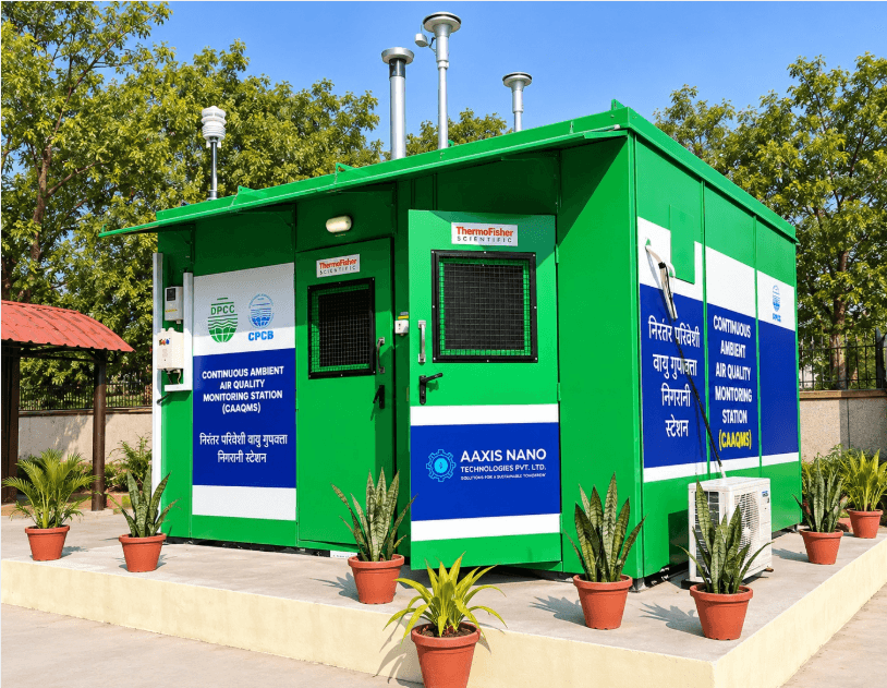
6 NEW CAAQMS STATIONS LIVE IN DELHI DPCC Strengthens Delhi’s Air Quality Monitoring Network 10 June 2026  |  Delhi Secretariat, India Enabled by Aaxis Nano’s integrated environmental monitoring and analytics capabilities, the CAAQMS network delivers real-time surveillance, automated reporting, and data-driven air quality management across Delhi. Six Continuous Ambient Air Quality Monitoring Stations (CAAQMS) were commissioned across Delhi, expanding the city’s real-time air quality monitoring network. The stations continuously monitor key pollutants including PM₂.₅, PM₁₀, NOx, CO, SO₂, O₃, NH₃ and BTEX, alongside critical meteorological parameters, generating validated environmental data every 15 minutes. Enabled by IoT-based communication and centralized analytics, the network supports real-time monitoring, AQI assessment, trend analysis, data comparison across locations, automated reporting, and direct CPCB server connectivity—strengthening data-driven environmental management and regulatory compliance across Delhi. Aaxis Nano executed the project on a turnkey basis, taking responsibility for the entire lifecycle—from supply and commissioning to operations and maintenance.  By combining environmental monitoring expertise with automation, IoT, and data analytics capabilities, the company provides integrated solutions that extend beyond equipment deployment to ensure reliable performance, data integrity, and long-term operational support. As urban air quality continues to remain a key environmental concern, the addition of six new monitoring stations marks a significant step towards building a more connected, data-driven, and responsive air quality management framework for Delhi.

UV Disinfection Systems for Water Treatment
Blogs, Water Quality Monitoring

UV Disinfection in Municipal Water Treatment: Why Utilities Are Moving Beyond Chlorination

Municipal water utilities today face a growing challenge: delivering safe drinking water while reducing chemical dependency, operational risk, and environmental impact. As cities expand and source water quality becomes more variable, utilities are moving beyond conventional chlorination alone and adopting advanced disinfection technologies that provide faster and more reliable pathogen control. One technology gaining widespread adoption is UV disinfection. By using ultraviolet light to inactivate harmful microorganisms without adding chemicals to the water, UV systems help utilities strengthen microbial protection, reduce disinfection by-products, and support regulatory compliance. Today, many of the world’s leading treatment facilities use UV as a critical barrier within a multi-stage treatment process. Why Conventional Chemical Disinfection Alone Has Limitations Chlorination continues to play an important role in water treatment because it provides residual protection throughout the distribution network. However, relying solely on chemical disinfection can present several operational and water-quality challenges.  Certain chlorine resistant pathogens such as Cryptosporidium and Giardia can survive standard chlorination doses. Chemical disinfection can also produce unwanted disinfection byproducts like trihalomethanes (THMs) and haloacetic acids (HAAs), especially when source water contains high organic content. In addition, chemical dosing systems require continuous handling, storage, and monitoring of hazardous substances. Variations in pH, turbidity, and organic load can also affect disinfection efficiency, making process control more complex for utilities operating large scale treatment networks. UV disinfection addresses many of these limitations by providing rapid microbial inactivation without altering the chemical composition of water. What is UV Disinfection? UV disinfection uses ultraviolet light, typically at a wavelength of 254 nanometres, to deactivate microorganisms by damaging their DNA and RNA structures. Once exposed to sufficient UV energy, bacteria, viruses, and protozoa lose their ability to reproduce and infect consumers. Unlike chemical disinfectants, UV treatment does not introduce additives into the water and does not generate harmful residual by-products under normal operating conditions.  Modern municipal UV systems are commonly installed after filtration processes and before final water distribution. In many treatment plants, UV acts as a primary disinfection barrier while chlorine provides secondary residual protection within the pipeline network. Core Components of a Municipal UV System A typical UV disinfection installation consists of several integrated components working together for controlled and validated pathogen inactivation. UV Reactors Water flows through stainless-steel reactor chambers containing multiple UV lamps arranged to maximise exposure throughout the flow path. Modern reactor designs are engineered to deliver consistent UV dose distribution even under varying flow conditions. UV Lamps Municipal systems typically use either Low-Pressure High-Output (LPHO) lamps or Medium-Pressure lamps. LPHO systems are known for their energy efficiency and longer operating life, while Medium-Pressure systems can deliver higher intensity output within a more compact footprint.  Quartz Sleeves UV lamps are enclosed within quartz sleeves that isolate electrical components from water while allowing maximum UV transmission. Maintaining sleeve cleanliness is essential for long-term performance.  UV Intensity Sensors Online sensors continuously monitor UV dose intensity to verify that disinfection performance remains within validated operating conditions. Control and Automation Systems Modern UV installations are closely integrated with PLC, SCADA, and telemetry platforms. Operators can monitor lamp performance, UV intensity, flow rates, alarms, and maintenance schedules in real time, enabling faster response to operational issues and improved process control. How UV Disinfection Works After coagulation, sedimentation, and filtration, water enters the UV reactor, where UV-C light damages microbial DNA, preventing replication. UV treatment effectiveness depends on: UV intensity Exposure time Water transmittance Modern UV systems automatically adjust lamp output based on flow and water quality, maintaining reliable disinfection while reducing energy use. Many municipal systems are validated to meet regulatory pathogen reduction requirements across a range of operating conditions, providing an added layer of treatment assurance. Key Advantages of UV Disinfection Effective Against Chlorine Resistant Pathogens UV systems are highly effective against Cryptosporidium and Giardia, which are difficult to fully control through chlorination alone. This makes UV particularly valuable for surface water treatment plants exposed to biological contamination risk. No Chemical Byproducts Since UV treatment does not involve oxidation reactions like chlorine, it significantly reduces the formation of THMs and HAAs, helping utilities meet stricter drinking water standards. Rapid Disinfection Microbial inactivation occurs within seconds as water passes through the reactor, enabling high throughput operation without large contact tanks. Improved Safety UV systems reduce dependence on hazardous chemical storage and handling, lowering operational risk for plant personnel. Compact Installation Compared to large chemical contact basins, UV reactors require relatively small installation footprints, making them suitable for both new plants and retrofit projects. Operational Challenges and Design Considerations Although UV disinfection offers significant advantages, system performance depends heavily on proper design and maintenance. Water Quality Dependence High turbidity, suspended solids, iron, manganese, and organic matter can reduce UV transmittance and shield microorganisms from exposure. Effective pretreatment is therefore essential. Lamp Fouling Mineral scaling and biofilm accumulation on quartz sleeves reduce UV transmission efficiency over time. Automatic mechanical or chemical cleaning systems are commonly used to maintain performance. Energy Consumption UV systems require continuous electrical power for lamp operation. Energy optimization strategies include variable lamp output control and reactor staging based on flow demand. No Residual Protection Unlike chlorine, UV leaves no residual disinfectant within the distribution network. Most municipal systems therefore use UV alongside low level chlorination or chloramination for downstream protection. Applications in Municipal Water Treatment UV disinfection is widely deployed across multiple municipal treatment scenarios: Surface water treatment plants Groundwater treatment facilities Recycled water and wastewater reuse projects Desalination plants Rural and decentralized drinking water systems Smart water infrastructure upgrades Large scale utilities increasingly integrate UV performance monitoring into centralized SCADA systems for real time operational visibility and compliance reporting. Industry Evolution Modern UV systems are becoming more intelligent and energy efficient through digital monitoring and automation. Advanced reactors now use real time UV transmittance compensation, predictive maintenance analytics, and remote performance diagnostics. Utilities are also integrating UV systems into broader smart water management platforms, combining water quality monitoring, hydraulic analytics, and automated reporting into unified operational dashboards. With tightening regulatory requirements and growing emphasis

E. coli and Coliform Monitoring
Blogs, Water Quality Monitoring

Real-Time E. coli and Coliform Monitoring in Drinking Water: Moving Beyond Periodic Lab Testing

In many Indian utilities, treated water quality is still monitored through periodic sampling and laboratory culture testing. Under BIS IS 10500:2012, neither E. coli nor total coliform organisms should be detectable in a 100 mL drinking water sample. When contamination is detected, utilities are expected to investigate and repeat sampling immediately. The operational challenge is response time. Conventional microbiological testing depends on bacterial culture growth, which typically requires 24 to 48 hours before results are available. By the time contamination is confirmed, the affected water may already have moved through the distribution network. As utilities move toward smarter water infrastructure, high-frequency automated microbial monitoring is emerging as an operational early-warning layer that improves visibility between laboratory sampling intervals. Why Periodic Lab Testing Falls Short Contamination events in distribution systems are often intermittent rather than constant. Short-duration events may occur due to: pressure transients, pipe leakage or intrusion, loss of chlorine residual, biofilm disturbance, maintenance activity, or localized network failures. A grab sample only reflects water quality at a single location and time. Conditions elsewhere in the network, or even a few hours later, may be very different. Because laboratory culture methods require incubation time, corrective actions are often reactive rather than preventive. Short-duration contamination events may remain undetected between scheduled sampling intervals. How Real-Time Monitoring Works Real-time monitoring takes a different route. Instead of waiting for whole bacteria to grow into colonies, it measures the enzymes they produce. Total coliforms carry β-galactosidase, and E. coli carries β-glucuronidase. Automated enzymatic analysers add fluorogenic reagents that react with these enzymes and generate a measurable fluorescence response associated with microbial contamination. An automated analyser runs this on site: it draws the sample, adds the reagent, incubates briefly, and reads the fluorescence. Systems such as ColiMinder can provide automated microbiological indication results in approximately 15 minutes and can support up to 56 automated measurements per day, with higher-frequency configurations available. This approach creates a near real-time operational visibility layer for drinking water systems. Core Technologies in a Deployment A working monitoring point usually combines a few layers: Enzymatic activity analysers that measure β-glucuronidase and β-galactosidase activity to flag faecal and coliform contamination quickly. ColiMinder is one such system, deployed by Aaxis Nano as part of its microbial monitoring offering. It operates fully automated on-site, drawing the sample, adding the reagent, and reading the fluorescence, making it suitable for continuous unattended deployment at treatment plant outlets, reservoir monitoring stations, and distribution network entry points. Supporting sensors for free chlorine, turbidity, pH, and conductivity, which add context, since a loss of disinfectant or a turbidity spike can signal conditions where bacteria may follow. Data loggers and RTUs that timestamp readings and send them over 4G/LTE, NB-IoT, or LoRaWAN. Cloud dashboards that track trends, apply threshold-based alerting, and generate operational notifications. Operational Benefits The payoff is speed. When detection falls from a day or two to about a quarter of an hour, an operator can isolate, flush, or re-chlorinate a section before bad water spreads. A continuous reading also helps tune disinfectant dosing, keeping chlorine neither unsafely low nor wastefully high. If something goes wrong, live data shows which zone is affected, keeping a boil-water advisory targeted rather than city-wide. High-frequency monitoring also supports monitoring documentation workflows and operational visibility.  Deployment Locations High-frequency microbial monitoring is commonly deployed at: Treatment plant outlets Reservoir inlets and outlets District metered area (DMA) entry points Post-disinfection verification stations Recycled water systems Pharmaceutical facilities Hospital water systems These locations provide earlier visibility into potential contamination events before broader network exposure occurs. How Aaxis Nano Supports Implementation Aaxis Nano supports utilities and industrial operators through telemetry integration, SCADA connectivity, and deployment of partner instrumentation platforms including ColiMinder, S::CAN, and ATI water quality monitoring systems.  Through its partnership with ColiMinder, it deploys automated enzymatic analysers that measure E. coli and coliform activity on site in about 15 minutes, providing higher-frequency operational visibility between laboratory sampling intervals. These analysers integrate with supporting instrumentation from partners such as S::can and ATi, with all data feeding into Aaxis Nano’s Telepro platform for  visualization, alerting, and SCADA integration. What Aaxis Nano’s Platform Delivers Aaxis Nano Hydrology Solutions supports utilities and industrial operators through telemetry integration, SCADA connectivity, and deployment of partner instrumentation platforms including ColiMinder, S::CAN, and ATI water quality monitoring systems. The company’s capabilities include: remote monitoring infrastructure, telemetry integration, cloud visualization, alarm management, dashboard configuration, SCADA integration, and operational monitoring support. By combining online instrumentation with centralized operational visibility, utilities can improve awareness of changing water quality conditions across distributed systems. FAQs Q1. How does an enzymatic analyser detect E. coli so quickly? E. coli produces the enzyme β-glucuronidase. Automated analysers use fluorogenic reagents that react with this enzyme and generate a measurable fluorescence signal associated with microbial contamination. Because the method measures enzymatic activity rather than waiting for bacterial colony growth, results can be generated much faster than traditional culture-based testing. Q2. Where should a utility install these instruments first? Typical starting points include: treatment plant outlets reservoir monitoring points DMA entry locations and post-disinfection verification stations Combining microbial monitoring with chlorine and turbidity monitoring improves operational context and incident detection capability

IoT-Based Water Monitoring
Blogs, Water Quality Monitoring

IoT-Enabled Water Quality Monitoring Systems for Real-Time Environmental Intelligence

Environmental water quality monitoring in India has traditionally relied on periodic manual sampling and laboratory analysis. While laboratory testing remains essential for regulatory validation, periodic sampling creates visibility gaps where short-duration contamination events, illegal discharge activity, and rapid water quality fluctuations may go undetected. As industrial activity, urban discharge, and groundwater stress continue to increase, utilities and environmental agencies are turning to continuous monitoring systems that combine online instrumentation, telemetry, and SCADA integration to improve operational visibility and response times. IoT-based water monitoring helps operators observe changing conditions in near real time, automate alerts, reduce field dependency, and support long-term environmental management strategies. The Limitations of Conventional Monitoring Traditional water quality assessment relies on grab sampling at fixed intervals. Samples are collected manually, sent to laboratories, and results return days later long after conditions on the ground have changed. This approach creates critical gaps. Short-duration pollution events between sampling cycles go unrecorded. Diurnal variations in dissolved oxygen, pH, or temperature remain invisible. Industrial effluent violations during off-hours avoid detection. The result is a monitoring framework better suited to documenting historical conditions than preventing environmental incidents. Geographic constraints further limit coverage. Remote river stretches, isolated groundwater wells, and distributed agricultural drainage points receive minimal monitoring due to the logistical costs of repeated field visits, leaving localized contamination zones undetected. Applications Across Environmental Domains River and Lake Monitoring: Continuous stations track water quality changes, detect tributary pollution loads, and provide early warnings for algal bloom formation. Groundwater Quality Networks: Submersible sensors in monitoring wells track aquifer chemistry, detect saltwater intrusion in coastal regions, and identify contamination from industrial or agricultural sources. Industrial Effluent Compliance: Since 2014, CPCB has mandated Online Continuous Effluent Monitoring Systems (OCEMS) for industries across 17 highly polluting categories, requiring real-time effluent data to be transmitted directly to CPCB and State Pollution Control Board servers. (Source) Wastewater Treatment Optimization: Sensor networks across treatment stages help operators adjust aeration, chemical dosing, and retention times based on real-time organic load data. Agricultural Runoff Assessment: Monitoring stations in drainage channels track nutrient and pesticide export during monsoon events, supporting better fertilizer timing and runoff management. How IoT-Based Water Monitoring Works Modern monitoring systems combine online sensors, telemetry infrastructure, cloud platforms, and SCADA integration to continuously collect and transmit operational data. A typical deployment includes: Multi-parameter water quality sensors Data loggers or RTUs Cellular or LoRaWAN communication systems Cloud dashboards and alerting platforms SCADA or control room integration Sensors installed at rivers, reservoirs, treatment plants, industrial discharge points, or groundwater wells continuously measure selected parameters and transmit data to centralized monitoring platforms. Core Sensing Technologies and Parameters Modern IoT-based monitoring systems deploy multi-parameter sensor probes that capture comprehensive water quality profiles. According to ISO 5667 water sampling standards, continuous monitoring should cover physical, chemical, and biological indicators. Physical Parameters: Temperature sensors with ±0.1°C accuracy track thermal patterns. Turbidity sensors using nephelometric methods (per ISO 7027 standards) measure suspended particles in the 0 to 1000 NTU range. Conductivity probes quantify total dissolved solids. Ultrasonic or radar sensors monitor water levels and flow velocity. Chemical Parameters: Optical luminescence sensors measure dissolved oxygen (0 to 20 mg/L range). Potentiometric electrodes track pH with ±0.02 unit accuracy. Ion-selective electrodes detect specific nutrients including nitrate, ammonia, and phosphate. Advanced deployments use spectroscopic methods for heavy metal detection (lead, cadmium, arsenic, chromium). Biological Indicators: Chlorophyll-a fluorescence sensors quantify algae biomass for eutrophication assessment. Rapid enzymatic assays detect coliform bacteria. Emerging biosensors enable pathogen-specific identification. Sensor probes connect to data loggers that perform edge processing (outlier filtering, drift compensation, diagnostics) before transmitting data via cellular networks (4G/LTE, NB-IoT), LoRaWAN for rural coverage, or satellite links for remote installations. Data Architecture and Analytical Approaches Field sensors capture measurements at intervals from one minute to one hour, depending on parameter stability and compliance requirements. Edge devices timestamp readings, apply quality control algorithms, and compress data before transmission. Cloud platforms ingest telemetry streams and apply multiple analytical layers: Threshold-Based Alerting: Real-time comparison against CPCB water quality criteria and BIS 10500:2012 drinking water standards. Exceedances trigger immediate notifications to operators and regulators. Statistical Process Control: Moving averages and control charts identify gradual deterioration before regulatory limits are breached, enabling predictive intervention. Machine Learning Models: Anomaly detection algorithms flag unusual parameter combinations indicating potential contamination. Regression models correlate upstream activities (rainfall, industrial cycles, agricultural seasons) with downstream impacts. Spatial Analysis: Kriging and inverse distance weighting generate continuous quality maps from discrete sensor locations, visualizing pollution gradients and identifying probable contamination sources. Continuous Water Monitoring Solutions by Aaxis Nano Aaxis Nano provides IoT-based water monitoring solutions through Telepro SCADA integration and partner instrumentation platforms including s::can, metriNet, Trojan UV Disinfection, and Sommer River Discharge Monitoring. PIPEMINDER-ONE data loggers are deployed for leak detection and pressure monitoring, while the telemetry architecture extends to multi-parameter water quality monitoring for surface water, groundwater, and industrial applications. The RADAR cloud analytics platform processes environmental sensor streams, applies threshold-based alerting aligned with Indian regulatory standards, and generates automated compliance reports. Integration capabilities support connections to state pollution control board servers, SCADA systems, and custom dashboards for utilities and industrial clients. Aaxis Nano’s solutions address Indian network conditions, supporting cellular connectivity across Tier 2 and Tier 3 cities, LoRaWAN for rural coverage, and hybrid strategies for challenging environments. Services include site assessment, sensor selection guidance, calibration protocols, and long-term maintenance planning. For utilities, industries, and environmental agencies transitioning from periodic sampling to continuous monitoring, Aaxis Nano offers deployment planning, system integration, and operational support. Future Direction of Continuous Monitoring As telemetry costs continue to decrease and communication infrastructure expands, continuous monitoring is becoming more accessible across utilities, industries, and environmental programs. Future improvements are expected in: remote diagnostics, lower-power instrumentation, improved sensor durability, cloud analytics, integrated operational visibility. However, successful deployments will continue to depend on practical operational factors including maintenance capability, communication reliability, and calibration management. Frequently Asked Questions Q1. How accurate are IoT sensors compared to laboratory testing? Modern sensors achieve accuracy comparable to laboratory methods for most regulated

IoT-Based Leak Detection Systems - water quality monitoring system
Blogs, Water Quality Monitoring

IoT-Based Leak Detection Systems for Smart Utilities

India’s water utilities continue to face high levels of Non-Revenue Water (NRW), where treated water is lost before reaching consumers. Many Indian water utilities continue to operate with NRW levels between 35% and 45%, reflecting significant losses from leakage, unauthorized consumption, and metering inefficiencies.  With NRW levels in many networks significantly above recommended benchmarks, utilities face rising operational costs, infrastructure stress, and increasing pressure on water resources. Why Conventional Leak Detection Struggles Conventional leak detection methods remain largely reactive, relying on visible leaks, customer complaints, or manual field inspections. As a result, many underground leaks remain undetected for days or weeks, leading to water loss, pipe deterioration, higher repair costs, and operational inefficiencies. Conventional leak detection methods remain largely reactive, relying on visible leaks, customer complaints, or manual field inspections. As a result, many underground leaks remain undetected for days or weeks, leading to water loss, pipe deterioration, higher repair costs, and operational inefficiencies. IoT-based leak detection solutions like PIPEMINDER combine  Minimum Night Flow (MNF) analysis, pressure transient monitoring, acoustic sensing, and flow monitoring to deliver continuous visibility across water networks. By correlating nighttime flow patterns with pressure and acoustic anomalies, utilities can identify hidden leaks, detect burst events early, and reduce long-term pipeline stress before failures escalate. The architecture is technology agnostic across pipeline types. It is deployed on potable water transmission and distribution mains, industrial process water systems, sewage networks, groundwater supply pipelines, and, with modified sensors, hydrocarbon and chemical pipelines. Core Technologies Used A typical deployment combines several sensor classes: Acoustic loggers (hydrophones) clamp onto pipes at valve chambers and hydrants, detecting the broadband noise signature in the 100 to 1,500 Hz range that pressurised leaks generate. Pressure transducers measure pipe pressure at up to 128 samples per second, capturing transient waves that travel at near sonic speed and indicate burst events or pipe fatigue. Electromagnetic and ultrasonic flow meters record inflow at District Metered Area (DMA) boundaries with accuracy of ±0.5 percent, forming the basis for leakage quantification. Remote Telemetry Units (RTUs) aggregate sensor data, perform edge processing, and manage wireless transmission via 4G/LTE, NB-IoT, LoRaWAN, or satellite, depending on network geography. Cloud analytics platforms ingest sensor streams, apply correlation and statistical models, and present results to operators through dashboards and SCADA integrations. How the System Works Field sensors continuously capture pressure, acoustic, and flow data. RTUs handle initial onboard processing, including timestamping, compression, and threshold based triggering. When an anomaly crosses a defined threshold, the logger switches to high resolution capture and prioritises that data for transmission, keeping bandwidth low and extending battery life in remote chambers. Processed data reaches the cloud platform, which runs three core analytical layers: Minimum Night Flow (MNF) analysis measures inflow into each DMA between 2:00 AM and 4:00 AM, when consumer demand is at its lowest. After subtracting legitimate night usage, the remaining flow represents background leakage. Trends over consecutive nights expose growing leaks before they escalate to failure. Acoustic correlation compares signals captured by two loggers on either side of a suspected leak zone. The time delay between arrivals identifies the leak location proportionally between the sensors, typically within 1 to 2 metres. Pressure transient analysis classifies waveform shapes to distinguish routine network events, such as pump starts and valve closures, from genuine pipe failure signatures, then triangulates the probable source. Confirmed events generate automated alerts via SMS, email, or direct SCADA push, with map pinpointed locations, severity grading, and full event data accessible through web and mobile dashboards. Operational Benefits The gains compound across several dimensions. Detection time drops from days or weeks to minutes or hours. Acoustic correlation significantly improves leak localization accuracy compared to conventional manual surveys, reducing excavation footprint and repair time.” Network coverage becomes continuous rather than route based. Continuous high-frequency pressure transient monitoring helps utilities identify pressure events associated with pipe fatigue and burst conditions in aging networks.  MNF analysis helps utilities identify background leakage trends across monitored zones. By combining continuous monitoring with targeted alerts, utilities can improve operational efficiency and prioritize field response more effectively.  Typical Applications Municipal potable water distribution is the largest use case, with acoustic loggers across valve chambers and pressure loggers at DMA boundaries. The same architecture supports several other domains: Industrial process water in pharma, chemicals, food processing, and power generation, where undetected leaks risk product contamination or unplanned shutdowns. Sewage and wastewater collection, where both infiltration (groundwater entering cracked pipes) and exfiltration (sewage leaking into groundwater) are monitored. Groundwater transmission mains crossing rural or remote terrain, typically deployed with satellite or LoRaWAN communication. Hydrocarbon and chemical pipelines, using sensors with infrared spectroscopy and laser induced fluorescence for safety critical monitoring. Smart city control rooms, where leak detection data feeds central infrastructure dashboards via open APIs. Deployment Considerations Most acoustic and pressure loggers mount externally at existing valve and hydrant access points, requiring no pipe cutting or excavation. This makes retrofit deployment viable on cast iron, ductile iron, asbestos cement, HDPE, and other legacy materials already in service. Communication selection depends on coverage and density. Urban areas with reliable cellular signal typically use 4G/LTE or NB-IoT. Semi-urban and rural networks benefit from LoRaWAN’s range and low power profile. Transmission mains beyond cellular reach require satellite telemetry. Effective DMA structure is a prerequisite, since networks without metered zone boundaries cannot run MNF analysis. SCADA integration paths should also be assessed early, since most modern platforms expose APIs and Modbus interfaces for direct connection. Industry Evolution Modern water networks are also evolving with predictive failure analysis, digital twins, and edge AI. Utilities now use historical sensor data and AI models to predict pipe failures, simulate network behaviour in real time, and enable faster leak classification directly at the device level, reducing response time and communication costs. How Aaxis Nano Supports Implementation Aaxis Nano delivers integrated pressure and leak monitoring solutions for smart utility networks using the PIPEMINDER leak detection and pressure monitoring solutions. Designed for continuous network visibility, PIPEMINDER-ONE data loggers monitor pressure transients and acoustic

Air Quality Monitoring, Blogs

Why AAQMS System Is Replacing Periodic Surveys

For years, air quality monitoring relied on periodic surveys collecting samples, analyzing them in labs, and generating reports days later. At one point, this approach was sufficient. But today, that model is increasingly misaligned with reality. Air pollution does not follow schedules. Emission levels fluctuate throughout the day due to traffic patterns, industrial operations, and environmental conditions. A single reading taken at a fixed time no longer reflects actual exposure or compliance status. This is why the conversation is shifting from whether to monitor to how continuously and accurately it can be done. The comparison between an AAQMS system vs periodic surveys is no longer theoretical; it directly impacts decision-making, compliance, and environmental control. Understanding the Two Approaches Before comparing, it is important to understand how each method operates in practice. Periodic Air Quality Surveys Periodic surveys involve: Manual collection of air samples Transporting samples to laboratories Analytical testing Report generation This method provides: High-accuracy readings (at a specific moment) Useful baseline data But it is inherently time-bound and discontinuous. AAQMS Systems (Continuous Monitoring) An Ambient Air Quality Monitoring System (AAQMS) continuously measures pollutant concentrations in real time. It monitors: PM2.5 and PM10 SO₂ NOx NO2 NO CO O₃ A typical AAQMS setup includes: Continuous analyzers Data acquisition systems Communication modules Centralized monitoring platforms Unlike surveys, AAQMS provides continuous, time-resolved data rather than isolated readings. AAQMS System vs Periodic Surveys: A Practical Comparison Factor Periodic Surveys AAQMS System Data Frequency Occasional snapshots Continuous real-time data Response Time Delayed (lab-based) Immediate Coverage Limited locations Multi-location monitoring Pollution Detection Misses fluctuations Captures real-time spikes Operational Effort High manual involvement Automated Decision Support Limited Data-driven This comparison highlights a fundamental shift, from reactive measurement to proactive monitoring. Where Periodic Surveys Fall Short in Real Operations The limitations of periodic surveys are not just technical, they are operational. 1. No Visibility Between Readings If sampling is done once a week or even once a day, any pollution spike outside that window goes unnoticed. Example: Industrial emissions spike at night Survey conducted during daytimeResult: No record of actual exposure 2. Delayed Decision-Making By the time lab results are available: The condition has already changed Corrective action is delayed This lag reduces the usefulness of the data. 3. Limited Use in Compliance Monitoring Regulatory frameworks increasingly require: Continuous data logging Transparent reporting Real-time access Periodic surveys struggle to meet these expectations consistently. 4. High Dependency on Manual Processes Sampling, handling, and analysis introduce: Human error Operational delays Inconsistent data quality Why AAQMS Systems Are Replacing Periodic Surveys The shift toward AAQMS is driven by practical advantages in real-world environments. 1. Continuous Monitoring Instead of Intermittent Data AAQMS systems track air quality every minute. This enables: Accurate trend analysis Identification of peak pollution periods Better understanding of pollution sources 2. Real-Time Alerts and Faster Response Instead of waiting for reports: Systems trigger alerts instantly Operators can take corrective action immediately This is critical in: Industrial zones Urban environments High-risk areas 3. Data-Driven Environmental Decisions Continuous data allows: Long-term trend analysis Predictive insights Improved planning Instead of reacting to past data, organizations can act on current conditions. 4. Integration with Modern Monitoring Systems AAQMS systems can integrate with: SCADA platforms PLC automation systems IoT-based dashboards This enables: Centralized monitoring Multi-location visibility Remote access When Periodic Surveys Still Make Sense Despite limitations, periodic surveys are not entirely obsolete. They are useful for: Baseline environmental studies Short-term research projects Calibration and validation of continuous systems However, they are no longer sufficient as a primary monitoring method. How Aaxis Nano Supports Advanced Air Monitoring Systems Aaxis Nano provides integrated environmental monitoring solutions designed for continuous and reliable data acquisition. Their approach includes: Deployment of AAQMS systems for real-time monitoring Integration with automation platforms and centralized dashboards Multi-location monitoring capabilities Scalable solutions for industrial and urban environments By focusing on system-level integration, Aaxis Nano enables organizations to move beyond fragmented monitoring toward structured, data-driven environmental management. The Future: Continuous Monitoring as a Standard Air monitoring is evolving rapidly. Future systems will focus on: Real-time public data access Integration with smart city infrastructure Predictive pollution analytics Networked monitoring systems In this landscape, continuous monitoring will not be an advantage, it will be a requirement. Conclusion: Choosing the Right Approach The comparison between the AAQMS system and periodic surveys is not just about technology, it is about effectiveness. Periodic surveys provide: Limited, time-bound insights AAQMS systems deliver: Continuous, real-time visibility Faster decision-making Better environmental control For organizations that need accuracy, responsiveness, and scalability, continuous monitoring is the logical step forward. Take the Next Step Toward Smarter Air Monitoring If your current monitoring approach relies on periodic data, it may not reflect actual conditions on the ground. A continuous monitoring system can provide: Better visibility Faster response More reliable data Looking to upgrade your air monitoring systems? Aaxis Nano can help you implement solutions tailored to your operational and environmental requirements. Frequently Asked Questions (FAQ) What is the difference between AAQMS and periodic surveys? AAQMS provides continuous real-time data, while periodic surveys offer limited, time-based readings. Why are AAQMS systems preferred today? They enable faster decisions, better compliance, and more accurate monitoring. Can periodic surveys replace AAQMS? No, they can only complement continuous monitoring systems. AAQMS provides continuous real-time data, while periodic surveys offer limited, time-based readings. They enable faster decisions, better compliance, and more accurate monitoring. No, they can only complement continuous monitoring systems.

Scroll to Top