Author name: admin

Blogs

Oil Spill Detection & Sensors: Real-Time Monitoring for Early Detection of Hydrocarbon Spills

Even a relatively small oil spill can spread rapidly across a water surface, driven by currents, wind, and tidal movement, making early detection the single most important factor in limiting environmental damage. Delayed detection allows oil to travel further from its source, contaminating larger areas of shoreline, marine habitat, and potentially drinking water intake points. Oil spill detection & sensors close this critical time gap by continuously monitoring vulnerable water bodies, ports, refineries, pipelines, and offshore platforms, for the earliest signs of hydrocarbon presence, often well before a spill would be visible to the human eye. This continuous vigilance matters most in exactly the locations where spill risk is highest: near loading terminals, along subsea and coastal pipelines, and around offshore drilling and production platforms, where a rapid alert can mean the difference between a quickly contained leak and a major ecological incident. How Oil Spill Detection & Sensors Work Oil spill sensors are designed to detect and quantify hydrocarbon presence in water by identifying the distinct physical and chemical properties that separate oil from water and other natural substances. Fixed sensors, such as the non-contact oil detectors from technology partner Laser Diagnostic Instruments (LDI), often mounted on buoys, pipelines, or dock structures, continuously sample the water surface or subsurface layer, watching for the optical, fluorescent, or spectral signatures characteristic of hydrocarbons. When a sensor detects a signal consistent with oil, it generates an alert that is transmitted to a remote monitoring platform, often accompanied by location data pinpointing exactly where the detection occurred. Some advanced systems pair a stationary detection platform with a deployable tracking buoy, released automatically upon detection, which floats with the oil slick to provide real-time data on the spill’s direction and speed of movement, giving response teams a head start on containment planning even before they arrive on site. Key Technologies in Modern Oil Spill Detection Sensors Modern oil spill detection relies on several complementary sensing technologies. Infrared spectroscopy identifies oil based on how it absorbs specific infrared wavelengths differently than water, allowing detection even in low-visibility conditions. Fluorescence and laser-induced fluorescence techniques, the core measurement principle behind LDI’s non-contact oil detectors, exploit the fact that many hydrocarbons fluoresce under specific light wavelengths, providing a highly sensitive method for distinguishing oil from other floating debris or natural organic matter, an important capability for minimising false alarms. Remote sensing technologies, including satellite-based sensors and drone-mounted cameras, extend detection capability across vast ocean areas that would be impossible to monitor with fixed sensors alone, supporting large-scale surveillance and spill tracking. Underwater and buoy-based sensors provide continuous, localized surveillance of high-risk zones such as port entrances and platform perimeters, often combined with sensors for water temperature and salinity to provide broader environmental context alongside the core hydrocarbon detection function. Applications of Oil Spill Detection & Sensors Across Industries Oil spill detection & sensors are deployed wherever hydrocarbon transport, storage, or processing creates spill risk. Ports and harbours use fixed buoy-based sensors to continuously monitor loading and unloading zones, where spill risk is highest during tanker operations. Pipeline operators deploy sensors along subsea and coastal pipeline routes to detect leaks early, often the first sign of a developing rupture before it becomes a major release. Offshore oil and gas platforms rely on continuous water-surface monitoring around rigs and production facilities, where rapid detection is critical given the difficulty of emergency response in open water. Refineries and industrial facilities with water discharge points use similar sensor technology, including ATEX-rated LDI detectors for hazardous zones, to catch accidental hydrocarbon releases into nearby water bodies before they travel downstream. In each case, the sensor network functions as a constant, automated sentinel, watching for the earliest indicators of a spill so human response teams can be mobilised immediately. Real-Time Monitoring: From Sensor Alert to Rapid Response The real value of oil spill detection & sensors lies in how quickly a detection translates into action. Real-time monitoring platforms aggregate data from multiple sensors across a site or region, applying alert thresholds that distinguish a genuine hydrocarbon detection from background noise or false positives. When a spill is confirmed, automated alerts, sent via SMS, email, or direct integration with a facility’s control room, ensure response teams are notified within moments rather than hours. Location-tagged detection points and, where deployed, tracking buoy data give responders a clear starting picture of the spill’s location and likely movement direction, allowing containment booms and cleanup resources to be positioned more effectively. This tight loop between detection and response is what ultimately determines how much environmental damage a spill incident causes. Choosing the Right Oil Spill Detection System Selecting an oil spill detection system depends on the specific risk profile of the site, since a port with frequent tanker traffic has different monitoring needs than a remote offshore pipeline route. Key considerations include the required detection sensitivity, the ability to differentiate oil from natural substances to minimise false alarms, communication range and reliability for remote locations, and integration with existing control room or SCADA systems for unified monitoring. Facilities operating in environmentally sensitive or high-traffic waters should prioritize systems with proven low false-alarm rates and rapid alert delivery, since the speed and accuracy of detection directly determines how effectively a spill can be contained before it spreads. Working with Aaxis Nano, backed by technology partner Laser Diagnostic Instruments (LDI), ensures detection sensitivity, sensor placement, and alerting architecture are engineered together for reliable, low false-alarm performance. Conclusion As oil and gas transport across oceans, pipelines, and inland waterways continues to grow, reliable oil spill detection & sensors remain one of the most effective safeguards against large-scale environmental damage. Aaxis Nano’s oil spill detection and hydrocarbon monitoring solutions, built on proven sensor technology from technology partner Laser Diagnostic Instruments (LDI), are engineered to deliver exactly this kind of real-time, dependable protection. Talk to our experts to evaluate your hydrocarbon spill monitoring requirements and design an oil spill detection network – with the correct sensor placement and alerting architecture – built for

Blogs, OCU- Odour Control Unit

Odor Control Units for STPs and Industrial Facilities: Technologies and Engineering Applications

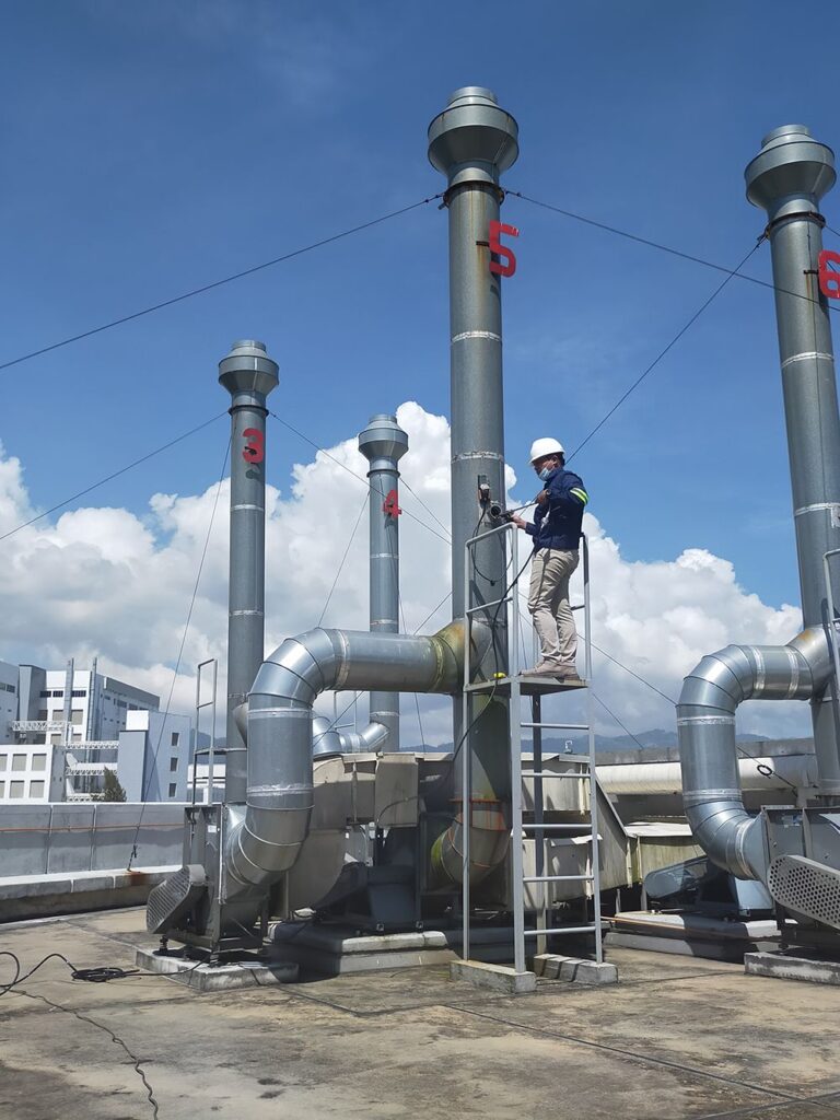
Sewage treatment plants and many industrial processes generate hydrogen sulfide and other volatile compounds as organic matter breaks down under anaerobic conditions. Beyond the obvious nuisance of foul smells, hydrogen sulfide is toxic at higher concentrations and corrosive to concrete and metal infrastructure, accelerating equipment degradation over time. As cities expand and STPs increasingly operate near residential zones, uncontrolled odor emissions can trigger community complaints, regulatory scrutiny, and even facility shutdown orders. Odor control units address this by continuously capturing and treating foul air before it is released, operating invisibly in the background, 24 hours a day, in some of the harshest environments a facility has to offer: high humidity, corrosive gas exposure, and constant operational demand. For plant operators, a well-engineered odor control unit is not just an environmental nicety, it is critical infrastructure that protects both public goodwill and the facility’s own equipment lifespan. How Odor Control Units Work: Core Technologies Explained Odor control units rely on several distinct treatment technologies, often used in combination depending on the odor load and gas composition. Chemical scrubbers pass foul air through a chemical solution, typically alkaline or oxidising, that reacts with and neutralises odour-causing compounds like hydrogen sulfide. Activated carbon filters, such as the Pure Air Solutions ACTUS® system, work through adsorption, trapping odor molecules within the porous surface of activated carbon media; this method is highly effective for a broad range of compounds but requires periodic media replacement. Biotrickling filters and biofilters, such as Pure Air Solutions’ SULPHUS® and ORGUS® systems, use a bed of organic material populated with odour-degrading microorganisms, which biologically break down odor compounds as air passes through, a low-chemical, energy-efficient option well-suited to continuous, moderate odor loads. Ozone and UV-based systems generate reactive oxidizing agents that break down odor molecules at a molecular level, offering fast treatment with minimal consumables but requiring careful system design to avoid excess ozone release. Many modern odor control installations combine two or more of these approaches to balance treatment effectiveness, operating cost, and reliability. Odor Control Units for Sewage Treatment Plants (STPs) At sewage treatment plants, odor typically originates from specific high-emission points: inlet chambers, screening and grit removal areas, sludge handling and dewatering units, and anaerobic digesters. Odor control units are usually deployed at these localised sources, with ductwork capturing foul air before it disperses into the wider plant environment. STP odour control chemicals, commonly used in scrubber-based systems, are selected based on the specific gas profile of the plant, since hydrogen sulfide concentrations and secondary odor compounds vary depending on influent characteristics and treatment stage. Because STPs operate continuously and cannot tolerate downtime in odor treatment without risking regulatory non-compliance or community complaints, odor control units for this application are engineered for redundancy and low-maintenance operation, often supported by remote monitoring so plant operators can track performance and anticipate media replacement or chemical dosing needs before a system failure occurs. Industrial Odor Control Units: Applications Beyond Wastewater While STPs are the most visible application, industrial odour control systems serve a wide range of sectors. Food processing and pharmaceutical manufacturing facilities use odor control units to manage process emissions and maintain compliance with environmental and occupational safety standards. Pump stations, critical nodes in sewage collection networks, typically require compact odor control solutions combining sealing, ventilation, and chemical treatment to prevent gas accumulation in confined, high-traffic urban locations. Even smaller-scale applications, such as compact odor control units for residential septic systems or private sewage outlets, use scaled-down versions of the same underlying technologies. Across all these use cases, the engineering principle remains consistent: capture the foul air at its source, treat it with technology matched to the odor profile and volume, and release clean air, all while operating reliably with minimal manual intervention. Engineering Considerations for Effective Odor Control Units Designing an effective odor control system requires more than selecting a treatment technology; it demands careful engineering of airflow, capture points, and system sizing. Undersized ductwork or poorly placed capture hoods can allow odors to escape before they ever reach the treatment unit, regardless of how effective the core technology is. Corrosion-resistant materials are essential given the constant exposure to hydrogen sulfide and moisture. Facilities should also account for peak-load events, such as sludge handling or tank cleaning, which can temporarily spike odor concentrations well above baseline levels. Since odor is measured in odor units per cubic meter or as specific gas concentrations in parts per billion, effective systems require periodic performance verification to confirm they continue meeting design targets as usage patterns and process conditions evolve over time. Choosing the Right Odor Control Unit for Your Facility The right odor control unit depends on your facility’s odor source, gas concentration, available space, and operating budget: chemical scrubbers suit high, variable odor loads; biofilters suit continuous moderate loads with lower chemical costs; and UV or ozone systems suit compact installations with limited ductwork space. Facilities operating STPs, pump stations, or industrial processes benefit from a custom-engineered approach rather than an off-the-shelf unit, since odor composition and volume vary significantly between sites. Partnering with Aaxis Nano, working with technology partner Pure Air Solutions ensures the odor control unit is sized, engineered, and maintained to perform reliably for years, protecting both community relationships and regulatory standing. Conclusion From STPs to pump stations to industrial process lines, odor control units are the invisible infrastructure protecting community relationships and regulatory compliance. Aaxis Nano, together with technology partner Pure Air Solutions, engineers chemical, biofilter, and UV-based odor control units tailored to each facility’s specific odor profile and operating conditions. Talk to our experts to evaluate your odor control requirements and design a biofiltration or scrubber-based treatment system – with the correct capture, ductwork, and treatment architecture – built for validated, auditable performance. Using proven odor control technology from technology partner Pure Air Solutions, Aaxis Nano provides system engineering, ductwork design, installation, commissioning, and lifecycle support across India. FAQs How do I know if I need a chemical scrubber or a biofilter? Chemical scrubbers,

Blogs, Gas Monitoring

Process Gas Analyzers: Applications in Combustion Efficiency, Process Control & Emission Monitoring

A process gas analyzer is an instrument that continuously measures the concentration of specific gases, such as oxygen, carbon monoxide, nitrogen oxides, or hydrocarbons, within an industrial gas stream. Unlike laboratory gas analysis, which involves collecting a sample and testing it separately, process gas analyzers operate in-line or via an extractive sampling system, delivering near-instant readings that feed directly into plant control systems. This real-time visibility matters because gas composition is often the earliest and most sensitive indicator of what is happening inside a combustion chamber or reactor, long before temperature or pressure changes become noticeable. By continuously tracking these gas concentrations, operators can catch inefficiencies, safety risks, or compliance breaches as they develop, rather than discovering them after the fact through periodic testing or equipment failure. How Process Gas Analyzers Improve Combustion Efficiency Combustion efficiency depends heavily on the ratio of fuel to air feeding a burner, boiler, or furnace. Too much excess air wastes energy by heating unnecessary volumes of gas; too little air leads to incomplete combustion, producing carbon monoxide and unburned hydrocarbons. Process gas analysers, such as the ABB EasyLine and Endura ranges, monitor oxygen, carbon monoxide, and combustible gas levels in flue gas streams, giving operators the data needed to fine-tune the air-fuel ratio in real time. This continuous feedback loop, often integrated directly with burner management systems, allows facilities to trim excess air to the optimal level, reducing fuel consumption and lowering the formation of nitrogen oxides, which increase sharply at higher combustion temperatures. Over the life of a boiler or furnace, even a small, sustained improvement in air-fuel ratio control translates into meaningful fuel savings and lower emissions. Process Gas Analyzers in Industrial Process Control Beyond combustion, process gas analysers play a critical role in controlling chemical and manufacturing processes where gas composition directly affects product quality or safety. In chemical plants, analysers track reactant and by-product gas concentrations to keep reactions within their optimal operating window, preventing off-spec production or hazardous build-up. In cement and metals manufacturing, gas analysers monitor kiln and furnace atmospheres to control oxidation states and ensure consistent material properties. Refineries and petrochemical facilities use hydrocarbon analysers to assess flare gas composition and optimise flare combustion efficiency, reducing both fuel waste and unburned hydrocarbon emissions. Integrating process gas analysers directly into distributed control systems or PLC-based automation allows these adjustments to happen automatically, minimising the need for manual intervention and reducing the risk of human error in safety-critical processes. Process Gas Analyzers for Continuous Emission Monitoring (CEMS) Regulatory bodies such as the CPCB and state pollution control boards require many industrial facilities, thermal power plants, cement plants, waste incinerators, and large boilers, to continuously monitor and report stack emissions. This is where Continuous Emission Monitoring Systems, built around process gas analysers such as the ABB Advance Optima AO2000 platform, become essential. CEMS-grade analysers measure pollutants such as NO, NO2, NOx, SO2, and CO in flue gas streams with high accuracy and fast response times, often reporting data every few seconds. This data is transmitted directly to regulatory servers, enabling authorities to track compliance in real time rather than relying on periodic manual stack testing. For facility operators, CEMS-integrated process gas analysers provide an early warning system: a rising trend in NOx or CO levels can be addressed operationally before it turns into a compliance violation. Key Technologies Behind Modern Process Gas Analyzers Process gas analysers use a range of measurement technologies suited to different gases and applications. Chemiluminescence is widely used for accurate NO, NO2, and NOx measurement in both ambient air and source emissions. Non-dispersive infrared and Fourier-transform infrared spectroscopy are common for detecting CO2, CO, and hydrocarbon gases by measuring how they absorb specific infrared wavelengths. Paramagnetic sensors are frequently used for oxygen measurement, since oxygen’s unique magnetic properties allow highly selective, drift-resistant detection. Flame ionisation detection, paired with gas chromatography, enables precise separation and measurement of methane versus non-methane hydrocarbons, important for both emission compliance and leak detection. Modern analyser platforms increasingly combine multiple detection technologies into a single modular unit, along with automatic calibration routines and self-diagnostic functions, reducing maintenance overhead while improving long-term measurement reliability. Selecting the Right Process Gas Analyzer for Your Facility Choosing the right process gas analyser starts with clearly defining the target gases, expected concentration ranges, and the harshness of the sampling environment, since high temperature, corrosive gases, or hazardous area classifications all influence analyser design requirements. Facilities operating in classified hazardous areas need analysers certified to ATEX, CSA, or equivalent standards, along with flame-arresting safety features. Response time requirements differ significantly between combustion optimisation, where seconds matter for control loops, and regulatory CEMS reporting, where accuracy and long-term stability are prioritised. Working with Aaxis Nano, in partnership with technology partner ABB, ensures the analyser, sampling system, and calibration protocol are engineered together, resulting in dependable, compliant, and efficiency-driving gas measurement for the life of the plan. Conclusion Whether the goal is trimming fuel costs, tightening process control, or satisfying CEMS compliance obligations, process gas analysers give plant operators the real-time visibility they need to run safer, more efficient, and more compliant facilities. Aaxis Nano’s range of process gas analysers and CEMS solutions, built on proven technology from technology partner ABB, is engineered for exactly these demands. Talk to our experts to evaluate your combustion efficiency, process control, or emission monitoring requirements and design a process gas analyser or CEMS installation – with the correct analyser technology and sampling architecture – built for validated, auditable performance. Using proven process gas analyser technology from technology partner ABB, Aaxis Nano provides system engineering, panel design, sampling system design, commissioning, and lifecycle support across India. FAQs What is the difference between a process gas analyzer and a CEMS? A process gas analyser is the measurement instrument itself, while a Continuous Emission Monitoring System (CEMS) is the complete regulatory-grade package built around one or more analysers, such as ABB’s Advance Optima AO2000 platform, including sampling, data logging, and reporting to pollution control boards.

Blogs

IoT & Data Loggers for Remote Environmental Monitoring: Connecting Field Sensors to Real-Time Dashboards

Traditional environmental monitoring relied on periodic manual sampling, a technician visiting a site, collecting a sample, and sending it to a lab for analysis days later. This approach leaves significant blind spots: a contamination event or equipment failure between visits can go undetected for days. IoT & data loggers close this gap by measuring parameters continuously and pushing data to central servers in near real time. Cellular (4G LTE, NB-IoT), radio, and satellite connectivity mean that even sites in remote, hard-to-access locations can report data as frequently as needed. Because IoT-enabled data loggers store readings locally and only need to transmit periodically, they remain functional even during temporary network outages. This combination of continuous sensing and resilient communication is why regulators and utilities are shifting from spot-check compliance monitoring toward always-on, IoT-driven remote environmental monitoring frameworks. How IoT Data Loggers Work: From Field Sensor to Cloud Dashboard An IoT-enabled environmental monitoring chain typically has four stages. First, a field sensor, measuring water level, pressure, temperature, gas concentration, or another parameter, generates a raw signal. Second, a data logger digitises and timestamps this signal, storing it locally in non-volatile memory as a safeguard against communication failure. Third, a telemetry module pushes the stored readings to a cloud platform using cellular, satellite, or radio protocols; some systems package this data as CSV files transmitted via FTP, while others stream it directly to an IoT hub. Finally, an application server validates the incoming data against expected ranges and station configuration before making it available through dashboards, automated alerts, and compliance reports. Modern loggers also support mobile app configuration via Bluetooth, GPS tagging for asset mapping, and integration with multiple communication protocols such as SDI-12, Modbus/RS-485, and 4-20mA, making them flexible enough to slot into both new deployments and existing SCADA infrastructure. Key Features to Look for in an IoT Data Logger Not all data loggers are built for the same conditions, so selecting the right one requires attention to a few critical features. Battery life matters enormously for remote sites; loggers with multi-year lithium battery life reduce the frequency of costly field visits. Build quality is equally important: titanium or IP68-rated, fully sealed enclosures ensure loggers survive submersion, corrosion, and temperature extremes in the field. Flexible connectivity, supporting SDI-12, Modbus/RS-485, and 4-20mA outputs, allows a logger to integrate with a wide range of sensors and existing telemetry or SCADA systems without custom engineering. Barometric compensation is essential for accurate water-level logging, particularly for non-vented sensors exposed to atmospheric pressure changes. Finally, look for smart addressing and auto-detection features, which simplify setup and let field teams swap sensors without reprogramming, reducing both deployment time and the risk of configuration errors. Applications of IoT & Data Loggers in Water Resource Management Water resource management is one of the largest applications for IoT & data loggers today. Groundwater level monitoring networks use rugged, submersible loggers, such as In-Situ’s TROLL series, to track aquifer trends over years, supporting sustainable extraction planning. Surface water and river-gauging stations rely on vented pressure loggers with automatic barometric compensation to deliver accurate stage readings for flood forecasting. In distribution networks, IoT-enabled loggers combined with leak-detection sensors help utilities identify pressure anomalies that indicate pipe leaks, reducing non-revenue water losses. For pollution control boards, real-time water quality monitoring systems built on IoT data loggers stream parameters like BOD, COD, and dissolved oxygen directly to regulatory servers, enabling continuous compliance oversight rather than periodic manual checks. Across all these use cases, the common thread is the same: connecting field-level sensors to a live, centrally accessible dashboard turns scattered data points into a coherent, actionable picture of water resources. Telemetry & SCADA Integration: Turning Data Loggers into Decision-Making Tools Data alone is not valuable until it is connected to the systems and people who need to act on it. This is where telemetry and SCADA integration come in. Cloud-based telemetry platforms aggregate incoming logger data, apply threshold-based alerting aligned with regulatory standards, and generate automated compliance reports for submission to pollution control boards. For industrial and utility operators, integrating data loggers with existing SCADA systems allows environmental readings to appear alongside process control data on the same operator dashboards, supporting faster, more informed responses. Real-time alerts, delivered via SMS or email, ensure that anomalies such as a sudden pressure drop or a parameter breach trigger immediate attention rather than being discovered during a routine report review days later. Building a Reliable Remote Environmental Monitoring Network with IoT & Data Loggers Deploying IoT & data loggers at scale requires more than good hardware; it requires a system designed end-to-end, from sensor selection and power management to telemetry architecture and dashboard configuration. Working with Aaxis Nano, in partnership with technology partner In-Situ, ensures loggers, communication protocols, and software are matched to the specific terrain, regulatory requirements, and operational goals of each site. As India’s water, air, and industrial monitoring networks continue to expand, IoT & data loggers will remain the connective layer that makes remote environmental monitoring not just possible, but practical, bringing field data into the hands of decision-makers in real time. Conclusion From groundwater wells to river gauges to industrial discharge points, IoT & data loggers are the connective tissue of modern environmental monitoring. Aaxis Nano’s telemetry-ready data loggers, powered by technology partner In-Situ, and Telepro platform are engineered to bring field-level data into real-time dashboards, wherever your sites are located. Talk to our experts to evaluate your remote monitoring requirements and design a telemetry-ready data logger network – with the correct sensor, communication, and power architecture – built for validated, auditable performance. Using proven data logger technology from technology partner In-Situ, Aaxis Nano provides system engineering, sensor integration, telemetry commissioning, and lifecycle support across India. FAQs What is the difference between a data logger and an IoT-enabled data logger? A standard data logger records and stores readings locally for manual download later, while an IoT-enabled logger, such as In-Situ’s VuLink or Level TROLL series, also transmits that data over cellular, satellite, or radio

AWS - Automatic Weather Station, Blogs

Weather Monitoring Systems: Key Components and Applications Across Agriculture, Weather Stations & Infrastructure

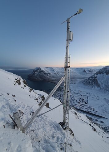
A weather monitoring system is an integrated network of sensors, data loggers, and communication devices that continuously measure and transmit meteorological parameters such as temperature, humidity, wind speed, wind direction, rainfall, and barometric pressure. Unlike manual weather observation, automated weather monitoring systems operate around the clock, capturing high-frequency data even in remote or hazardous terrain.Sensors mounted on a mast or tower collect raw signals, which are digitised and stored by an onboard data logger. This data is then transmitted – via GSM/GPRS, satellite, or radio – to a central server where it is validated, visualised, and made available through web dashboards or mobile apps. The result is a continuous stream of ground-truth weather intelligence that supports early warning systems, operational planning, and long-term climate studies. Key Components of a Modern Weather Monitoring System Every reliable weather monitoring system is built from a set of core components engineered to work together under demanding field conditions. Meteorological sensors-including ultrasonic anemometers for wind speed and direction, capacitive humidity sensors, piezoelectric pressure transducers, and precision temperature probes-form the sensing layer of the system.  Data loggers capture sensor readings at defined intervals, apply timestamps, and store data locally as a backup in case communication is interrupted. Telemetry and communication modules, whether GSM/GPRS, satellite, or radio links, transmit field data to central servers, which is particularly important for stations located in remote or high-altitude terrain. Solar panels paired with battery backups keep stations operating autonomously in locations without grid access, while IP-rated, ruggedised housings and masts protect sensitive electronics from rain, dust, and temperature extremes.  Finally, cloud-based visualisation software converts raw data into graphs, alerts, and historical trends for decision-makers. Together, these components form a resilient measurement chain from the physical sensor in the field to the dashboard on an analyst’s screen. Weather Monitoring Systems in Agriculture: Protecting Yield and Resources In agriculture, weather monitoring systems play a direct role in improving productivity and reducing losses. Farmers and agri-businesses use real-time temperature, humidity, rainfall, and wind data to schedule irrigation more precisely, reducing water waste while protecting crops from drought stress. Humidity and temperature readings also feed into pest and disease forecasting models, allowing early intervention before an outbreak spreads across a field. Wind speed data supports safer and more effective pesticide spraying schedules, minimizing drift and off-target application. During harvest season, short-term rainfall forecasts derived from field-level weather stations help farmers time their harvest to avoid crop damage. As precision agriculture adoption grows across India, weather monitoring systems are increasingly integrated with soil moisture sensors to build a complete picture of field conditions, turning weather from an unpredictable risk into a manageable variable. Weather Monitoring Systems for Infrastructure: Roads, Rail & Renewable Energy Beyond agriculture, weather monitoring systems are critical for protecting infrastructure exposed to extreme or variable weather. Road and rail authorities deploy weather stations along vulnerable corridors to detect icing, heavy rainfall, or high winds that could compromise safety, feeding directly into early-warning and maintenance-dispatch systems. In the renewable energy sector, wind farms rely on precise wind speed and direction data to optimize turbine performance and forecast power generation, while solar installations use irradiance and temperature readings to predict output and schedule maintenance. High-altitude and alpine regions depend on ruggedized automatic weather stations from technology partner Sommer to support avalanche warning services and protect mountain roads and rail lines. In each of these cases, the value of a weather monitoring system lies not just in the data itself, but in how quickly that data reaches the people who need to act on it. Automatic Weather Stations: The Backbone of Weather Monitoring Networks At the core of most large-scale weather monitoring networks is the automatic weather station (AWS), a self-contained unit designed for long-term, unattended operation in extreme conditions. Built for durability, these stations combine solar-powered operation with rugged, IP-rated enclosures so they can function reliably in alpine, coastal, or desert environments without infrastructure support. Their modular design allows wind sensors and other instruments to be customised based on application, from basic temperature and rainfall monitoring to comprehensive suites covering wind, solar radiation, and atmospheric pressure. In cold and high-altitude regions, weather stations are often deployed alongside a dedicated snow monitoring system to track snowpack alongside standard meteorological parameters. Automatic weather stations, such as the Sommer AWMS range, are typically networked together into a distributed monitoring system, with each station transmitting data to a shared central platform, allowing meteorological departments and infrastructure operators to build wide-area weather visibility without needing to manually visit each site. Choosing the Right Weather Monitoring System for Your Application Selecting a weather monitoring system requires matching sensor capability, ruggedness, and communication infrastructure to the specific environment and use case. Agricultural deployments may prioritise cost-effective, easy-to-maintain stations with irrigation-relevant parameters, while infrastructure and disaster-management applications demand IP-rated, all-weather durability and near-real-time telemetry. High-altitude or remote deployments should factor in solar autonomy and satellite communication where cellular coverage is unreliable. Equally important is long-term calibration and maintenance support, since sensor drift over time can quietly erode data quality and undermine decision-making. Working with Aaxis Nano, in partnership with technology partner Sommer, ensures that hardware selection, installation, and software integration are engineered together, resulting in a weather monitoring system that delivers dependable data for years, not just months. Conclusion As weather variability continues to affect agriculture, infrastructure, and public safety across India, investing in a robust weather monitoring system is no longer optional; it is foundational risk management. Whether the goal is optimising irrigation, protecting a rail corridor, or supporting an avalanche warning network, the right combination of sensors, telemetry, and software transforms raw atmospheric data into timely, actionable intelligence.  Talk to our experts to evaluate your weather monitoring requirements and design an automatic weather station network – with the correct sensor, telemetry, and power architecture – built for validated, field-proven performance. Using proven automatic weather station technology from technology partner Sommer, Aaxis Nano provides system engineering, station design, sensor integration, commissioning, and lifecycle support across India. FAQs What parameters does

Case Studies

From STPs to Continuous Water-Quality Visibility: Aaxis Nano Advances Monitoring Across the Ganga Basin

102 Online Continuous EFFLUENT MONITORING SYSTEMS From STPs to Continuous Water-Quality Visibility: Aaxis Nano Advances Monitoring Across the Ganga Basin 11 September 2026  | Uttarakhand, Bihar & Jharkhand, India Namami Gange Programme | Uttar Pradesh & West Bengal | 51 STPs | 102 OCEMS Sets | 5-Year O&M The Project Aaxis Nano Technologies completed the supply, installation and commissioning of Online Continuous Effluent Monitoring Systems (OCEMS) across 51 Sewage Treatment Plants (STPs) in the Ganga River Basin, spanning Uttar Pradesh and West Bengal. Completed in 2025, the project combines continuous water-quality measurement with field data acquisition, digital connectivity and sustained technical support. A Regional Monitoring Infrastructure The deployment comprises 102 OCEMS sets across 51 STPs, with two monitoring systems installed at eachplant—one at the inlet for influent monitoring and one at the outlet for treated-effluent monitoring. Aaxis Nano’s scope covered supply, installation, testing, commissioning, trial operation and five years of comprehensive operation and maintenance, establishing standardized OCEMS infrastructure across multiple locations in Uttar Pradesh and West Bengal. Instrumentation Behind the System The field architecture integrates specialized instrumentation for measurement, analysis and communication. ph::lyser provides continuous pH measurement, while spectro::lyser enables UV-VIS spectral sensing for multi-parameter water-quality analysis. ammo::lyser supports online ammonium (NH₄- N) and ammonia measurement, while con::cube manages system control, data processing and communication. Continuous Measurement of Critical Parameters The installations measure Flow, pH, BOD, COD and TSS, with designated Category-I installations additionally covering Ammoniacal Nitrogen and Nitrate Nitrogen.  The systems incorporate multipoint calibration, automatic water-matrix adaptation and data-validation capabilities to support reliable analytical performance. From Field Data to Centralized Visibility Data generated at individual monitoring stations is connected to central infrastructure, supporting raw and validated data transmission, multi-server connectivity, remote system access and two-way communication. GPS-based station identification, operational logs, and calibration and validation records provide additionalvisibility into system status and data quality. Sustaining Performance Beyond Commissioning The connected monitoring network is supported by five years of comprehensive operation and maintenance, extending Aaxis Nano’s involvement beyond commissioning and providing continued technical support throughout the O&M period. The Outcome The 51-STP OCEMS network brings continuous water-quality information from geographically distributed treatment plants into a connected monitoring framework. This enables centralized access to field data, validated measurements and system status, strengthening real-time visibility and supporting sustainedmonitoring of treated-effluent quality across the Ganga River Basin. Aaxis Nano Technologies Pvt. Ltd. Effluent Monitoring | OCEMS | Water Quality Monitoring | Data Acquisition & Connectivity | Real- Time Monitoring | Environmental Monitoring | Automation

Case Studies

From Effluent Monitoring to Centralized Visibility: Aaxis Nano Advances Monitoring Across 39 STPs

78 Online Continuous EFFLUENT MONITORING SYSTEMS From Effluent Monitoring to Centralized Visibility: Aaxis Nano Advances Monitoring Across 39 STPs 11 September 2026  | Uttarakhand, Bihar & Jharkhand, India Namami Gange Programme | Uttarakhand, Bihar & Jharkhand | 39 STPs | 78 OCEMS Sets | 5-Year O&M The Project Aaxis Nano Technologies completed the supply, installation and commissioning of Online Continuous Effluent Monitoring Systems (OCEMS) across 39 Sewage Treatment Plants (STPs) spanning Uttarakhand, Bihar and Jharkhand in the Ganga River Basin under the Namami Gange Programme. Completed in 2025, the project connects distributed effluent monitoring with Ganga Plus, a centralized monitoring platform for real-time data visibility, analytics, alerts and reporting. Distributed Effluent Monitoring Across 39 STPs The deployment comprises 78 OCEMS sets across 39 STPs, with two monitoring sets installed at each plant—one at the inlet to monitor influent and one at the outlet to monitor treated effluent. The monitoring architecture combines analytical and sensor-based systems with local data acquisition andautomatic cleaning provisions to support continuous field operation. Continuous Measurement of Critical Parameters The OCEMS network continuously monitors key effluent-quality parameters including Flow, pH, BOD, COD and TSS across the connected STPs. At the 30 Category-I STPs, TN (eq) is additionally monitored, while the 9 Category-II STPs monitor Flow, pH, BOD, COD and TSS. Ganga Plus: From Field Data to Centralized Intelligence At the centre of the monitoring architecture is Ganga Plus, the Central Monitoring Station and dashboarddeveloped for centralized real-time monitoring and analytics. The platform brings data from distributed STP installations into a common digital environment, enabling: Real-time site visibility and geographic visualization Parameter-level monitoring Alerts and alarms Data validation and annotations Customized reporting Time-series data management Remote configuration Data transfer to CPCB/SPCB systems Built on an IoT-based architecture with secure digital communication and API-based data exchange, Ganga Plus provides a scalable foundation for connected STP monitoring and centralized environmental data management Built for Long-Term Monitoring The project includes five years of comprehensive operation and maintenance, supporting continued operation of the OCEMS installations and centralized monitoring infrastructure. The long-term service scope supports system performance, data availability and continuity of monitoring across the connected STP network. The Outcome The 39-STP OCEMS network and Ganga Plus CMS establish a connected digital monitoring framework that brings field-level effluent data into a centralized environment. This strengthens visibility, data-driven oversight and regulatory monitoring across the connected STP network. Aaxis Nano Technologies Pvt. Ltd. Effluent Monitoring | Central Monitoring Systems | IoT & Digital Solutions | Data Acquisition | Real- Time Analytics | Environmental Monitoring | Automation

Case Studies

From River Flow to Reliable Discharge Data: Aaxis Nano Advances Monitoring on the Brahmani River

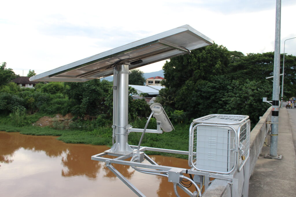
DISCHARGE MONITORING From River Flow to Reliable Discharge Data: Aaxis Nano Advances Monitoring on the Brahmani River 08 September 2026  | Odisha, India Brahmani River, Jajpur, Odisha | Government of Odisha – Department of Water Resources | Completed 2025 The Project Aaxis Nano Technologies completed the supply, installation, testing and commissioning of a Non-Contact Type Discharge Measurement System for the Government of Odisha, Department of Water Resources, atthe Brahmani River in Jajpur district. The project was executed under the Jaraka Irrigation Division and completed in 2025. The Monitoring Requirement Reliable river-discharge information is an important input for water-resource and irrigation monitoring. At the designated Brahmani River location, the requirement was to establish a dedicated system for measuring river discharge without direct contact with the flowing water. The Aaxis Solution Aaxis Nano deployed a non-contact discharge measurement system designed to capture river-flow information without placing measurement equipment directly in the flowing water. This provides a dedicated discharge-monitoring capability at the river location while supporting ongoing water-resource monitoring requirements. From Deployment to Operational Readiness Aaxis Nano’s scope covered the complete deployment lifecycle: Supply of the discharge measurement system Site installation Testing Comissioning Training Maintenance Provisions This end-to-end execution supported the operational readiness of the installed system. The Outcome The deployment adds non-contact river-discharge measurement infrastructure to the Brahmani River in Jajpur district, strengthening the availability of river-flow information for water-resource and irrigationmonitoring activities and ongoing operational requirements. Aaxis Nano Technologies Pvt. Ltd. Water Resource Monitoring | Discharge Measurement | Instrumentation | Real-Time Monitoring | Data Acquisition | Automation

Case Studies

From Mine-Site Emissions to Continuous Air Quality Visibility: Online Monitoring at Khanak

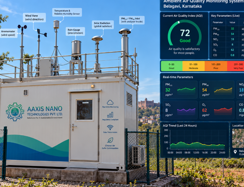
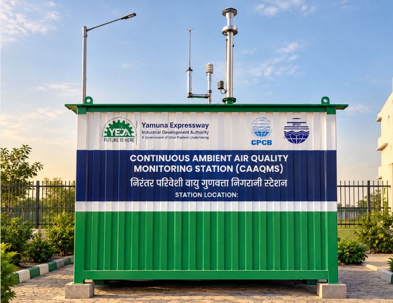
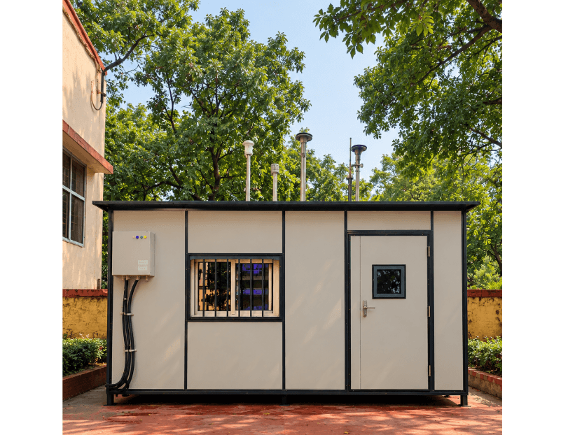
3 AMBIENT AIR QUALITY MONITORING SYSTEMS From Mine-Site Emissions to Continuous Air Quality Visibility: Online Monitoring at Khanak 07 September 2026  | Haryana, India 3 Monitoring Sites | 5 years O&M | 24×7 Operations Aaxis Nano Technologies has successfully installed three Online Ambient Air Quality Monitoring Stations (OAAQMS) at the Khanak mine site in Haryana. Completed in 2026, the engagement covers the complete delivery lifecycle—from equipment supply and site installation through testing, commissioning, trial operation and long-term operation and maintenance. Monitoring for the Mining Environment The stations provide continuous ambient air-quality monitoring across the designated monitoring locations. The monitoring scope addresses air-quality conditions associated with mining activities, transportation and the use of heavy machinery within the impact zone. Measuring Critical Air-Quality Parameters The systems monitor key ambient air-quality parameters including PM₁₀, PM₂. ₅ , NO₂, CO and SO₂, following the applicable NAAQS framework and specified measurement methodologies. This provides continuous measurement of the parameters defined for monitoring at the site. Connecting Measurements with Data The solution extends beyond measurement to make monitoring information accessible for operational and regulatory use. Data is digitally displayed at the main mine-site gate and supported through daily, monthly and yearly reporting and data storage. Online data transfer to HSPCB/CPCB platforms is also part of the system requirements. Beyond Commissioning Aaxis’ engagement continues through 5 years  of operation and maintenance, supporting the monitoring stations throughout their operational life. The O&M scope includes preventive and scheduled maintenance, annual maintenance, breakdown response and OEM-sourced spares to support sustained system availability. The operating framework also provides for 24×7 staffing, with dedicated supervisory and operator/lab-technician personnel supporting the stations. By combining deployment expertise with sustained technical support, Aaxis helps deliver monitoring systems designed for continuous, dependable operation in demanding field environments Aaxis Nano Technologies Pvt. Ltd. Environmental Monitoring | IoT & Digital Solutions | Real-Time Monitoring | Data Acquisition & Connectivity | Remote Monitoring | CAAQMS

Blogs, Gas Monitoring

How Real-Time Gas Monitoring Prevents Industrial Accidents Before They Happen

Toxic and flammable gas leaks remain one of the leading causes of industrial accidents in sectors like chemicals, oil and gas, fertiliser manufacturing, and pharmaceuticals. The gap between a leak starting and a leak being noticed is often where the real damage happens. Real-time gas monitoring closes that gap by continuously sampling the plant atmosphere and triggering alarms the moment concentrations cross safe thresholds – long before human senses would detect a problem. This blog looks at how real-time gas monitoring works, what it’s built from, and why it has become a non-negotiable layer of industrial safety. Regulators, insurers, and internal safety audits are all converging on the same expectation: hazardous gas exposure should be caught by instruments, not by incident reports. That shift is what makes real-time gas monitoring one of the highest-return safety investments a plant can make. What Is Real-Time Gas Monitoring and Why Industrial Plants Need It<span style="font-style: inherit Real-time gas monitoring refers to the continuous, automated detection of hazardous gases – flammable, toxic, or oxygen-displacing – using fixed or portable sensors placed at strategic points across a facility. Unlike periodic manual checks with handheld meters, real-time gas monitoring never stops watching, which matters because many industrial leaks (a corroded valve, a failed seal, a pressure surge) can escalate from a minor release to a dangerous concentration within minutes. Plants handling ammonia, chlorine, hydrogen sulphide, methane, or volatile organic compounds are especially exposed, since several of these gases are colourless, and some are also odourless at hazardous concentrations, making automated detection the only reliable early warning. How Real-Time Gas Monitoring Detects Hazards Before They Escalate A real-time gas monitoring system works by continuously drawing ambient air (or sampling directly at the sensor location) and measuring gas concentration against pre-set thresholds – typically expressed as a percentage of the Lower Explosive Limit (LEL) for flammable gases or as parts per million (ppm) for toxic gases. When readings cross a warning or alarm threshold, the system immediately triggers audible/visual alarms, notifies the control room, and can even initiate automated responses such as activating exhaust fans, shutting valves, or halting specific processes. This automated escalation path is what separates real-time gas monitoring from manual inspection: the system reacts in seconds, while a scheduled walk-around might not catch the same leak for hours. Key Components of a Real-Time Gas Monitoring System Fixed gas detectors: permanently installed sensors at high-risk points such as compressors, storage tanks, pipelines, and confined spaces. Portable gas detectors: worn by personnel entering confined spaces or performing maintenance in variable-risk zones. Central controller/alarm panel: aggregates sensor data, manages alarm logic, and interfaces with the plant’s DCS or SCADA system. Communication and telemetry: transmits sensor data to control rooms and, where required, to remote monitoring dashboards. Automated response interlocks: pre-configured actions such as ventilation activation or emergency shutdown triggered by specific alarm levels. A well-designed real-time gas monitoring network combines fixed and portable detectors so both stationary equipment risk and personnel exposure risk are covered. Industries That Benefit Most from Real-Time Gas Monitoring Oil, gas and petrochemicals: monitoring for hydrocarbons, hydrogen sulphide, and combustible vapours around wellheads, pipelines, and storage. Chemicals and fertiliser plants: detecting ammonia, chlorine, and other process gases around reactors and storage tanks. Pharmaceutical manufacturing: monitoring solvent vapours and oxygen levels in cleanrooms and confined processing areas. Power and energy: detecting combustible gas build-up around turbines, generators, and fuel handling systems. Water and wastewater treatment: monitoring hydrogen sulphide and methane in sewage pumping stations and digesters. Across all these sectors, real-time gas monitoring is increasingly tied to both worker safety mandates and insurance/audit requirements, making it as much a risk-management tool as a compliance one. Best Practices for Deploying Real-Time Gas Monitoring Systems Conduct a hazard mapping study to identify likely leak points before deciding sensor placement. Select sensor types (catalytic, infrared, electrochemical) matched to the specific gases present at each location. Set tiered alarm thresholds – early warning and critical alarm – rather than a single trigger point. Integrate real-time gas monitoring with the plant’s SCADA/DCS so alarms and shutdown logic are centrally visible. Maintain a calibration and bump-test schedule, since sensor drift can silently reduce detection reliability. Skipping calibration is one of the most common ways a real-time gas monitoring system loses effectiveness over time, so it should be built into the maintenance calendar, not treated as an afterthought.   Real-Time Gas Monitoring and Regulatory Compliance in India Indian factories and hazardous process units fall under the Factories Act, the Manufacture, Storage and Import of Hazardous Chemicals Rules, and sector-specific PESO/OISD guidelines, several of which reference continuous gas detection as part of on-site emergency preparedness. Real-time gas monitoring data also supports statutory safety audits, on-site emergency plans, and insurance risk assessments, giving plants a documented safety record beyond the immediate goal of accident prevention. Choosing the Right Real-Time Gas Monitoring Partner Because sensor accuracy, placement, and response logic all determine whether a real-time gas monitoring system actually catches a leak in time, plants should work with a partner experienced in both the instrumentation and the process risks of their specific industry. This includes conducting a proper hazard survey, recommending the correct sensor technology for each gas, and providing ongoing calibration support rather than a one-time installation. Aaxis Nano supplies and commissions real-time gas monitoring systems for chemicals, fertiliser, oil and gas, and wastewater treatment facilities across India, pairing certified analysers and detectors with field engineering support so plants get a system that is correctly specified, properly maintained, and ready to perform when it matters most. Conclusion Industrial accidents involving gas leaks rarely happen without warning signs – the challenge is catching those signs before they become emergencies. Real-time gas monitoring gives plants a continuous, automated safety net that detects hazardous concentrations within seconds and triggers a response faster than any manual process could. For high-risk sectors like chemicals, oil and gas, and pharmaceuticals, investing in a properly designed and maintained real-time gas monitoring system is one of the most effective ways to

Scroll to Top